De0-Nano-SoC soc_system compilation
soc_system compilation
Pre-steps and disclaimer
In this step I assume that you already created a custom FPGA component, if not one is provided for you under the name custom_leds (this is part of the RocketBoards guide demo that you can browse to get more knowledge about the whole process. In a later post we will go more in-depth on the Avalon interfaces topic, but for now our focus is on synthesizing the system in Intel’s Platform Designer tool.
Platform Designer
When we are finally satisfied with our component’s FPGA code, we should first of all Analyze and Synthesize it, and once we don’t get any compilation errors or warnings about latches or any other side-effects of our meticulous or sloppy coding, we are good to go!
I like to keep the IP component in a separate directory (in this case under hardware) and also I create a separate project for every component I synthesize and test. When adding a cusotom component to the system, the files will get copied over so don’t fret.
Open the Platform Designer tool and choose the pre-created soc_system.qsys file. It will load the default configuration of the system with many components already connected and ready to go. We need first create a block of our component and then integrate it (connect the relevant signals and interfaces, map memory and interrupts).
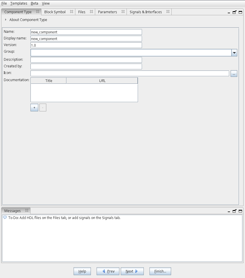
You will be greeted by such window:
Then, add a new component:
Add all the necessary files:
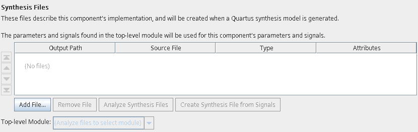
When you read all the files, press “Analyze Synthesis Files” and observe that no errors are displayed. If all ran successfully, you will have some signals and interfaces inferred for you. You can also add various simulation files but I left that empty.
Some input and output signals should be inferred and are visible as shown below:
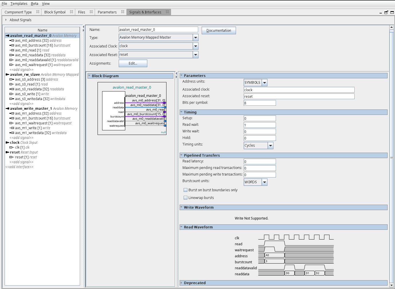
In case you are defining some Avalon or AXI interfaces, Platform Designer will kindly inform you about missing/wrong signals, as well as telling you that your direction of the signal might be wrong
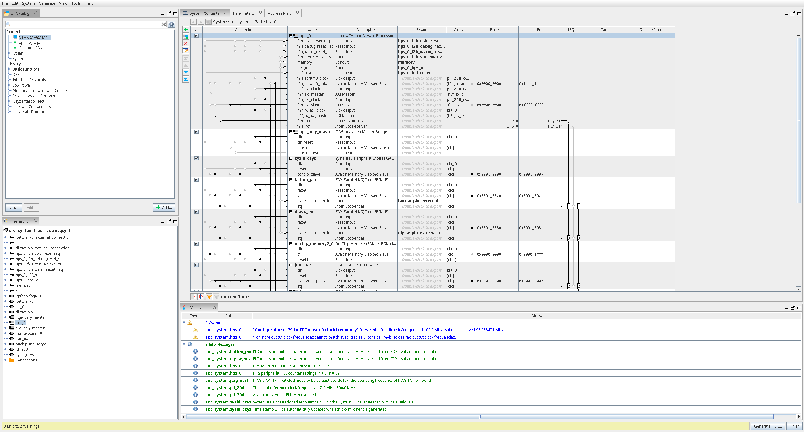
After the component has been created, add it to the system view and connect relevant signals by pressing on the interconnect between them on the left side of “System Contents” window. If you want to export some signals to be visible outside the HPS IP, you may do so by double-clicking in the “Export” column.
Memory addresses can be assigned either in the “System Contents” window or in the “Address Map” window. Be sure to not overlap any other peripherals and systems.
To finish, press “Generate HDL” button and once it is done exit the program. You can now view the resultant soc_system.v file that contains your component. Remember to run “Compile Design” to generate the FPGA programming file.
Putting the code on the FPGA
Now we can put our code on the board - all we need to do is convert our .sof file into a raw binary file - .rbf. Quartus contains necessary tools for that so we just have to put the proper version of our binary.
After converting the binary we should put the soc_system.rbf into our SD card directory:
cp soc_system.rbf sd_card/sdfs
Signaltap usage
In case not everything runs as smoothly as you predicted or you just want to see your signals you can use the Signaltap software. Unfortunately, when you use the free Quartus License you will need to recompile everything from scratch once you decide to change a signal to track, so be warned.
In the main window you first should add the relevant clock, set the sample depth (how many samples do we want to store simultaneously), choose the triggers and add signals you want to observe. I found a short video that explains this very concisely.
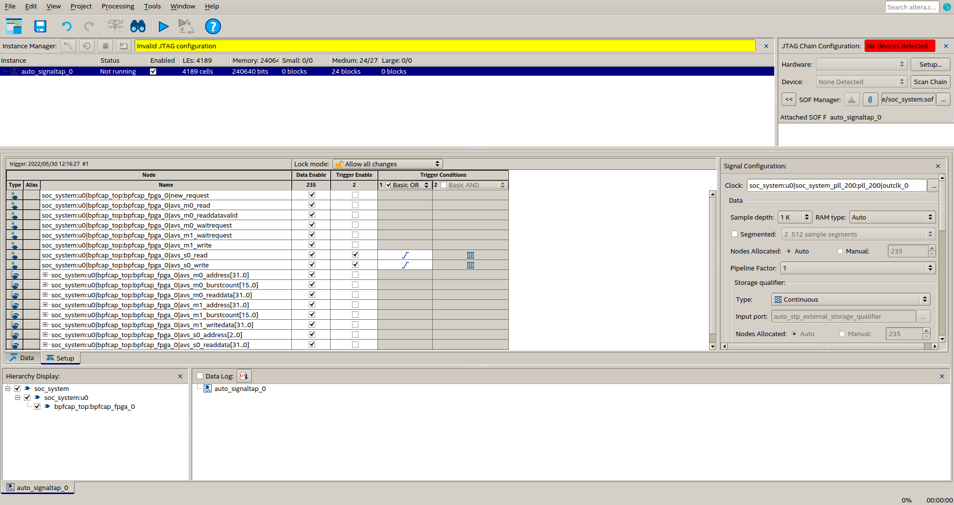
You can enable/disable signals and trigger whether they should trigger (no pun intended) the capture. You also can change the triggering conditions so be sure to check that.
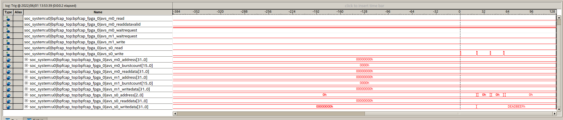
Each time you reset the board, be sure to flash the signaltap .sof file onto the board and start capturing of the samples. The window with the results is visible below, you can see that we have three Avalon MM writes to the Agent (or in old terms - Slave) device: